Cold Storage Cooling System Project Overv
Welcome to our comprehensive introduction to a recently completed cold storage cooling system project. Designed and implemented to meet rigorous standards, this project demonstrates our expertise in delivering tailored refrigeration solutions. Below are the key highlights of the system:
System Specifications
- Compressor Unit:
- Type: Screw Compressor Unit (Bitzer HSK)
- Cooling Capacity: xx kW/unit
- Operating Parameters: Evaporation Temperature (Te) = +5°C, Condensation Temperature (Tc) = +40°C
- Cooling Coils:
- For Cold Storage Rooms:
- Quantity: 6
- Brand: Guentner
- Cooling Capacity: xx kW/coil (Te = +5°C, Room Temp = +15°C)
- For Pharmaceutical Storage:
- Quantity: 1
- Brand: Guentner
- Cooling Capacity: 10 kW/coil (Te = +5°C, Room Temp = +15°C)
- For Cold Storage Rooms:
- Heat Rejection System:
- Cooling Towers: Liangchi (2 Units)
- Capacity: 60 RT/unit
- Cooling Water Pumps: Ebara (2 Units: 1 Operational, 1 Standby)
- Cooling Towers: Liangchi (2 Units)
- Control System Components:
- Valves & Controllers: Full suite of gas and water valves, along with advanced control devices.
- Central Control Panel: Houses both power and control modules for streamlined system operation.
- Installation Materials:
- Refrigerant and water piping with insulation.
- Power and control cables.
- Refrigerant gas, lubricant, and other auxiliary materials for a fully integrated system.
System Design Documentation and Resources
To ensure operational efficiency and provide comprehensive support, we deliver a range of detailed documents and design resources, including:
- Process & Instrumentation Diagram (P&ID): Provides an overview of control principles and operational logic.
- 3D and Layout Drawings: Includes detailed 3D models (Revit –
.rvt) and electrical cabinet layouts (AutoCAD –.dwg).
- Wiring Diagrams: Detailed diagrams for power and control connections (EPLAN –
.zw1and.elb). - Operational Manual: A step-by-step guide for system operation and maintenance (Word format).
- Source Code for Automation Systems:
- HMI Design Files: HMIGTO interface designs (Vijeo Designer –
.projectarchive).
- HMI Design Files: HMIGTO interface designs (Vijeo Designer –
- SCADA Configuration: Machine SCADA Expert files (
.app). - PLC Programming Code: M241 PLC programs (Machine Expert –
.projectarchiveand.project).
Key Benefits
This system ensures optimal cooling performance for both general cold storage and sensitive pharmaceutical storage requirements. The implementation of high-efficiency equipment and advanced automation technology reduces energy consumption and operational costs while maintaining precise temperature control.
By leveraging innovative design and robust engineering, this project sets a benchmark in cold storage solutions.
For more information, or to discuss your refrigeration needs, contact us today!
Process & Instrumentation Diagram (P&ID): Overview of Control Principles and Operational Logic
The P&ID for this project provides a detailed representation of the cold storage cooling system’s process flow, instrumentation, and control architecture. Below, we outline the key functions and operational logic of each major component in the system.
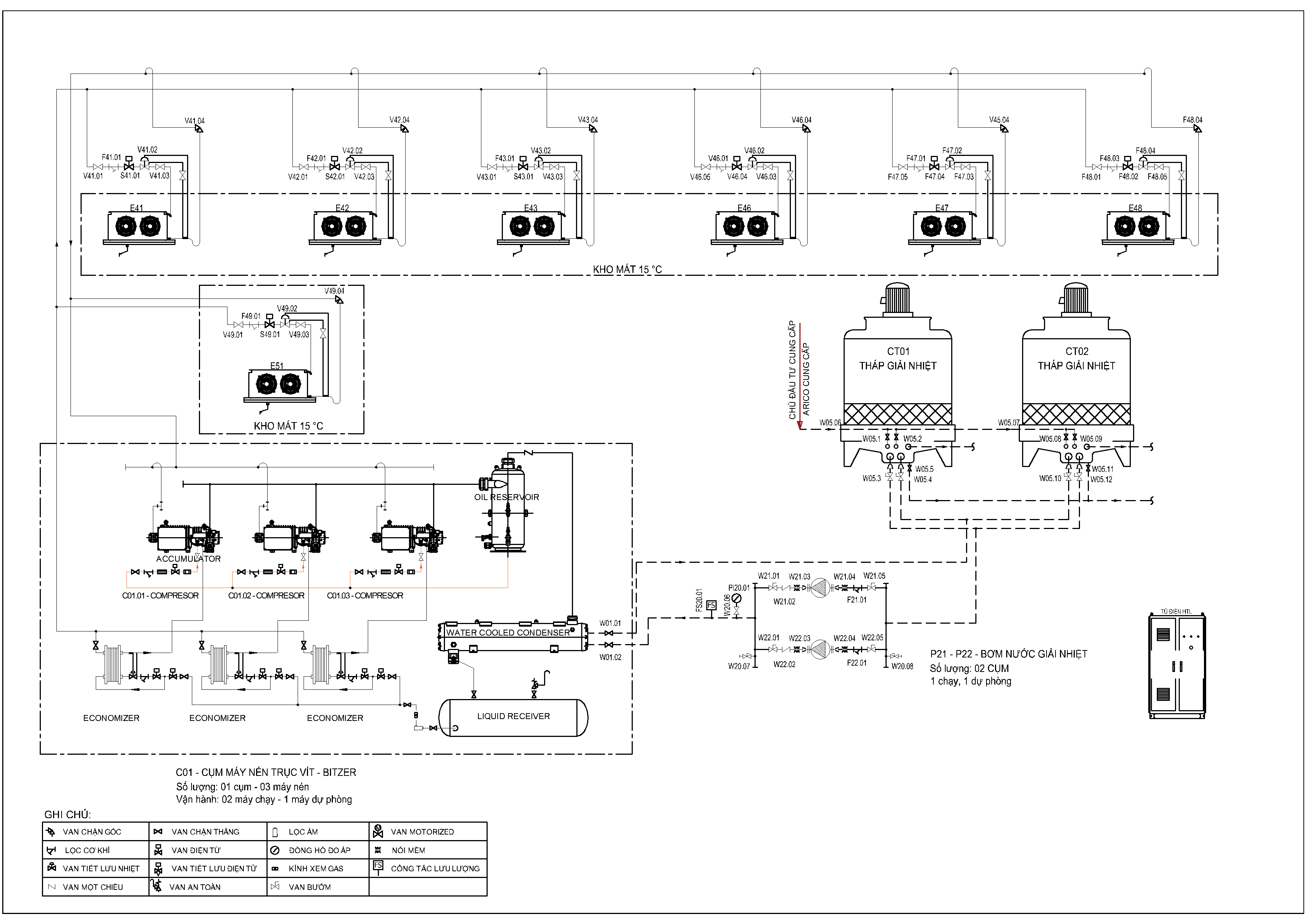
1. Function of the Compressors
- Compressors Overview:
- The system includes one compressor unit with three Bitzer HSK6451-50 screw compressors, designed for water-cooled operation.
- Control Logic:
- Compressor #1 (VFD-Controlled):
- A Variable Frequency Drive (VFD) modulates the speed of this compressor to dynamically adjust to load variations, ensuring precise temperature control and energy efficiency.
- Compressor #2 and #3 (PW-Controlled)
- These compressors operate on Part-Winding starting, based on system demand, controlled by the PLC logic.
- Compressor #1 (VFD-Controlled):
- Key Roles:
- Compressors maintain system pressure by compressing low-pressure refrigerant gas from the evaporators into high-pressure gas for condensation.
2. Function of Air Coolers (Cooling Coils)
- Cooling Coils Overview:
- 6 Air Coolers for General Storage Rooms:
- Designed for +15°C storage conditions, each coil has a cooling capacity of 35 kW.
- 1 Air Cooler for Pharmaceutical Storage:
- Maintains sensitive conditions at +15°C, with a 10 kW capacity.
- Control Logic:
- Gas flow to each air cooler is regulated by solenoid valves and expansion valves.
- Temperature sensors (RTDs or thermocouples) in the storage rooms provide feedback to the PLC to modulate gas flow.
- Defrost cycles, if required, are activated periodically by the control system using electric heating or hot gas defrost methods.
- 6 Air Coolers for General Storage Rooms:
3. Function of the Heat Rejection System
- Cooling Towers:
- Two Liangchi cooling towers (60RT each) dissipate the heat absorbed by the refrigerant via water-cooled condensers.
- Fans in the cooling towers operate under the PLC’s control, adjusting their speed to maintain consistent water outlet temperatures.
- Cooling Water Pumps:
- Two Ebara pumps ensure continuous circulation of cooling water between the condensers and cooling towers.
- The lead pump operates continuously, while the backup pump is activated in case of a fault or increased demand.
4. Function of Valves
- Gas Valves (Liquid Line):
- Solenoid valves control the flow of refrigerant to the air coolers.
- Thermostatic or electronic expansion valves regulate refrigerant expansion to achieve the desired evaporation temperature.
- Water Valves:
- Motorized valves control water flow to maintain optimal heat exchange in the condensers.
- Safety valves and check valves ensure pressure stability and prevent reverse flow.
5. Function of the Control Panel
- Overview:
The central control panel integrates the entire system, facilitating automated and manual control modes. - Components and Their Roles:
- VFD for Compressor #1:
- Adjusts the compressor speed to achieve load-based cooling control.
- PLC (Schneider M241):
- Core controller that processes data from sensors, actuates valves, and manages the overall system logic.
- Communicates with SCADA and HMI systems via Ethernet/IP protocols.
- HMI (HMIGTO, 12 inches):
- Provides a user-friendly interface for local monitoring and control of the system.
- Displays key parameters such as temperatures, pressures, and system alarms.
- SCADA (Machine Expert SCADA):
- Advanced supervisory system with 4000 tags for remote monitoring and control.
- Offers real-time data visualization, trend analysis, and alarm management.
- Power and Protection Modules:
- Includes circuit breakers, overload relays, and soft starters for safe and reliable operation.
- VFD for Compressor #1:
Control Logic Summary
- Start-Up Sequence:
- System initializes by activating the cooling water circuit.
- Compressors and air coolers are then brought online based on cooling demand.
- Temperature and Load Regulation:
- Room temperature sensors provide continuous feedback to the PLC.
- The PLC modulates the operation of compressors, air coolers, and cooling towers to maintain setpoints.
- Defrost and Maintenance Cycles:
- Automated defrost cycles prevent ice accumulation on air coolers.
- The system generates alarms and logs when maintenance is required for key components.
- Safety and Emergency Control:
- Safety devices (high/low-pressure switches, safety valves) ensure the system operates within safe limits.
- The control system initiates an emergency shutdown in case of critical faults.
By leveraging advanced automation and robust engineering, this system achieves efficient, reliable, and flexible cooling for both general and pharmaceutical storage needs. The P&ID serves as a comprehensive guide for operation, maintenance, and troubleshooting.
3D and Layout Drawings: Overview and Details
The 3D and layout drawings are essential for providing a comprehensive visualization of the cold storage cooling system and ensuring efficient installation and maintenance. Below is a breakdown of the provided resources and their significance:

1. Detailed 3D Models (Revit – .rvt)
- Purpose:
The 3D Revit models offer a detailed and interactive visualization of the entire refrigeration system, including spatial arrangements, equipment placement, and piping networks. These models facilitate coordination among project stakeholders and ensure that the design complies with spatial and operational requirements. - Key Components Represented in 3D Models:
- Compressor Unit:
- Accurate representation of the Bitzer HSK6451-50 screw compressors, including dimensions, connections, and maintenance access areas.
- Air Coolers:
- Placement and orientation of all 7 Guentner air coolers within the storage rooms, showing their airflow patterns.
- Cooling Towers and Pumps:
- Placement of the Liangchi cooling towers and Ebara pumps, along with detailed pipe routing for cooling water circuits.
- Refrigerant Piping:
- 3D routing of refrigerant lines with insulation, showing connections between compressors, condensers, and air coolers.
- Electrical Conduits and Cabling:
- Detailed routing of power and control cables, ensuring no interference with piping or other system components.
- System Clearances:
- Includes minimum clearances for maintenance and operational safety, adhering to regulatory standards.
- Compressor Unit:
- Annotations and Tags:
- Equipment tags, piping specifications, and valve identifiers are included in the 3D models for easy reference.
- Annotations detail pipe diameters, insulation thickness, and refrigerant flow directions.
- Benefits of the 3D Models:
- Enables clash detection to identify and resolve potential conflicts during the installation phase.
- Facilitates virtual walkthroughs for stakeholders to understand the system layout.
- Supports future expansions or modifications by providing an accurate as-built reference.
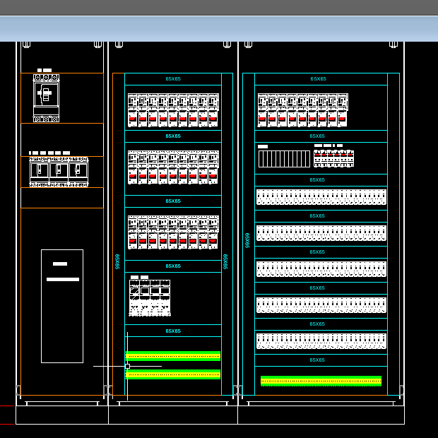
2. Electrical Cabinet Layouts (AutoCAD – .dwg)
- Purpose:
The AutoCAD layouts provide a detailed design of the electrical cabinets, showcasing the arrangement of power and control components for the entire system. - Key Details in the Cabinet Layout Drawings:
- Power Distribution Panel:
- Representation of circuit breakers, contactors, relays, and overload protection devices.
- Layout optimized for easy access to high-power components like the VFD for Compressor #1.
- Control Section:
- Integration of the Schneider PLC M241, HMIGTO (12-inch HMI), and SCADA connectivity modules.
- Wiring and connections for all temperature sensors, pressure switches, and actuators.
- Power Distribution Panel:
- VFD Integration:
- Dedicated section for the VFD controlling Compressor #1, including proper ventilation and cable routing to minimize EMI (Electromagnetic Interference).
- Cable Termination:
- Clear labeling and routing of incoming and outgoing cables for power, control, and communication.
- Color-coded wiring for AC, DC, and signal lines as per international standards.
- Annotations and Labels:
- Includes labels for each component with references to their functions (e.g., MCB for Compressor #2, Ethernet switch for SCADA).
- Detailed cross-references to wiring diagrams for seamless integration with other system documentation.
- Benefits of the Cabinet Layout Drawings:
- Simplifies troubleshooting and maintenance by providing a clear representation of component placements.
- Reduces installation errors with precise cable routing and labeling.
- Ensures compliance with safety and electrical standards
Integration Between 3D Models and Layout Drawings
The 3D Revit models and AutoCAD cabinet layouts are fully integrated to ensure consistency across the mechanical and electrical aspects of the system:
- Spatial Coordination:
- The 3D models include the location of electrical cabinets relative to the refrigeration equipment for streamlined installation.
- Wiring and Conduit Routing:
- Conduit paths shown in the 3D models are cross-referenced with the electrical cabinet layouts to ensure alignment.
- As-Built Documentation:
- Post-installation updates to both the 3D models and layouts ensure accurate as-built documentation for future reference.
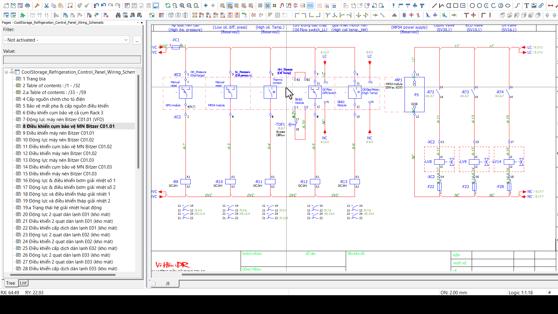
Wiring Diagrams: Detailed Power and Control Connections (EPLAN – .zw1 and .elb)
The wiring diagrams are crucial for the electrical and automation setup of the cold storage cooling system. Designed using EPLAN, they provide a detailed representation of all electrical connections for power, control, and communication circuits, ensuring precise implementation and troubleshooting.
1. Purpose of the Wiring Diagrams
- Power Distribution:
Clearly illustrate the electrical supply to all components, including compressors, air coolers, cooling towers, and water pumps. - Control Circuits:
Outline connections for sensors, actuators, PLC, HMI, and SCADA systems. - Communication Networks:
Display the integration of communication protocols for remote monitoring and control. - Safety and Protection:
Highlight critical protective measures such as fuses, breakers, and overload relays.
2. Key Sections of the Wiring Diagrams
a. Power Supply and Distribution
- Main Power Supply:
- Incoming 3-phase power supply with voltage ratings and earthing details.
- Representation of main circuit breakers and distribution panels.
- Compressor Wiring:
- Power connections for the VFD-controlled Compressor #1 and PW-controlled Compressors #2 and #3.
- Motor terminals (U, V, W) and control wiring for motor starters.
- Air Coolers and Auxiliary Loads:
- Individual power circuits for the seven air coolers.
- Connection details for defrost heaters (if applicable).
- Cooling Towers and Pumps:
- Wiring for cooling tower fan motors and the lead/standby water pumps.
b. Control Circuits
- PLC Connections:
- Input/output (I/O) modules mapped to sensors, actuators, and alarms.
- Connections for room temperature sensors, pressure switches, and flow meters.
- HMI (HMIGTO 12-inch):
- Power and Ethernet connections to the PLC for local monitoring and control.
- VFD for Compressor #1:
- Wiring of analog/digital signals for speed control and fault feedback.
- SCADA Integration:
- Ethernet connections between PLC, SCADA system (Machine Expert SCADA), and network switches.
- Valves:
- Wiring for solenoid valves and motorized water valves, including control signals from the PLC.
c. Communication Networks
- Fieldbus Configuration:
- Ethernet/IP and Modbus TCP/IP networks for communication between the PLC, SCADA, and HMI.
- Daisy-chained connections to sensors and actuators where applicable.
- Tagging and Addressing:
- Detailed identification of each communication node and its corresponding I/O point in the control system.
d. Safety Circuits
- Emergency Shutdown (ESD):
- Hardwired ESD circuit connected to all critical equipment.
- Protection Devices:
- Fuses, thermal relays, and surge protectors.
- Interlocks to prevent unsafe operation.
3. Features of the EPLAN Files (.zw1 and .elb)
- Smart Wiring Assistance:
- Auto-routing suggestions for optimal cable length and layout.
- Cross-References:
- Cross-referenced components and terminals for quick identification across different sheets.
- Color-Coded Wires:
- Wires are color-coded for easy differentiation between power, control, and communication circuits.
- Component Symbols:
- IEC-standard symbols for switches, relays, sensors, and actuators.
- Terminal Strip Diagrams:
- Clear layout of terminal blocks for ease of wiring and future maintenance.
4. Benefits of the Wiring Diagrams
- Installation:
Simplifies the installation process by providing clear and accurate wiring details. - Troubleshooting:
Speeds up fault identification and repair with labeled connections and cross-references. - Scalability:
Allows easy integration of future expansions or upgrades. - Regulatory Compliance:
Ensures adherence to electrical standards and safety regulations.